A Procedural City
(May 2015)
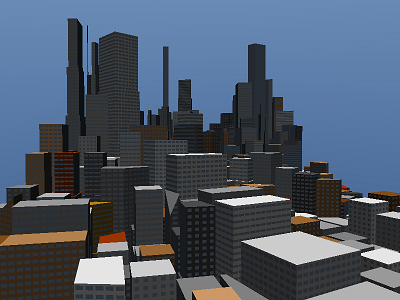
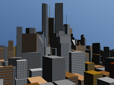
For the third year module titled 'Procedural Methods' an application was developed with Visual Studio 2010 in c++ using DirectX11 which allows users to fly through a procedurally generated city and view the steps taken to generate the building plots. The city visibly changes during a day-night cycle as the building's windows light up as the sun sets. The main procedural content within the application is the generation of the building plots and the buildings themselves. The lighting of the windows are not done procedurally during the application but utilised self-made textures created in GIMP.
Generating the Building Plots
The first step to generating the city is generating the building plots. A city is split into districts, districts are split into blocks, and blocks are split into plots. These plots provide the boundaries for the generated buildings.
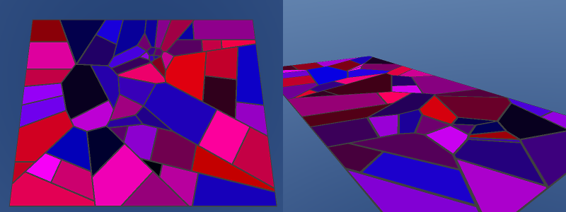
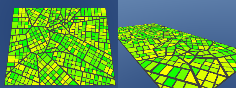
The perimeter of the city is defined by a randomly sized quad. Voronoi points are placed inside the quad to create voronoi regions which become the districts. A city can have one, two or three focus points where buildings reach a peak height. The voronoi points are strategically placed around these focus points with half of the points placed within a small circle around the focus points and the other half placed further away from the focus points. The vertices of the voronoi regions are calculated using a half plane intersection algorithm from Mui (2001). The algorithm uses the intersections of perpendicular bisectors between every voronoi point to locate the vertices.See Figure 1 for two examples of the generated districts.

Once the vertices of each voronoi region has been calculated the districts can then be divided into blocks. This is done by sweeping across a district in the direction of one randomly picked edge and splitting the district into blocks of varying widths. These blocks are then swept along in the perpendicular direction, splitting them into smaller blocks of varying sizes. The edges of the blocks are then brought inwards to make room for main roads between the blocks. If a block is now too small it is removed. See Figure 2 for examples of the districts in Figure 1 split into blocks.
The blocks in each district are then split into long plots of equal width by sweeping across them in the same direction used to sweep across the district. This keeps all of the plots edges within a district parallel. The long plots are then swept across in the perpendicular direction to create smaller plots of equal width. At the end of a sweep if there is not enough space left to divide a district/block into another block/plot then the final block/plot is left as a larger block/plot. The edges of the plots are then brought inwards by half the width of the roads. This widens the width of the main roads between the blocks as well as creating roads between the plots. This provides a distinction between major and minor roads. See Figure 3 for examples of the blocks in Figure 2 split into plots.
Generating the Buildings
Number of Storeys
The height of a building is defined as a number of storeys. Buildings are assigned a height between fifty and ninety storeys with one in five buildings being assigned a height between ninety and one hundred and ten storeys. The height is then reduced based on the distance from the building plot to the nearest focus point.
Building Colour
All buildings above sixty storeys are a shade of grey. Buildings below sixty storeys have a two in three chance of being a shade of grey. The remaining buildings above thirty storeys will be a sandy colour. The remaining buildings below thirty storeys have a two in three chance of being a sandy colour otherwise there is a fifty percent chance they will be either a shade of red or a shade of yellow.
Triangular Building Plots
On a plot with three vertices buildings are constructed by extruding the plot upwards to the height of the building. Two in Three roofs are left flat while the remainder can be slopped in one of two ways. The first method staggers the height of the vertices of the roof by raising one by an eighth the height of the building and another by a quarter. The second method raises two vertices of the roof by a quarter the height of the building.
Quadrilateral and Other Polygonal Building Plots
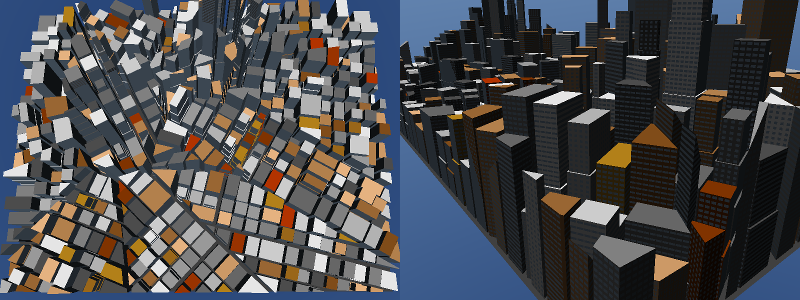
On plots with four or more vertices buildings can be constructed in two ways. The first method extrudes the plot upwards to the height of the building and leaves it with a flat roof. The second method splits the building into multiple segments of equal heights. The plot is extruded upwards to a fraction of the buildings height. A new segment is placed on top with the vertices of its base brought inwards and then extruded upwards again. New segments are added until the top of the building has been reached. The number of segments in a building is random and dependant on the height of the building. If an extruded segment is too narrow it is removed and the previous segment is extruded to the top of the building. See Figure 4 for examples of buildings placed on the plots from Figure 3.
Windows
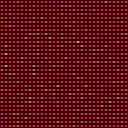
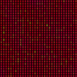
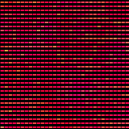
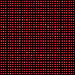
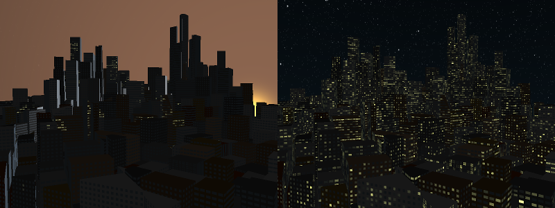
There are four types of window textures which are randomly assigned to buildings based on the height of the buildings. See Figure 5 for examples of the different window types. Each texture is a grid of 64 by 64 windows. A large number of windows per texture hides the pattern of the lit windows since the walls of buildings do not have the same uv texture coordinate starting position. All four textures have slightly different sized windows with one containing crossed windows. The red channel of the textures is used to define whether it is a window or a wall. If the red channel is zero then the building receives its own wall colour. During the day all windows are given a standard colour. During the night the colour of the windows are lit up based on the value in the green channel. The brighter the green channel the brighter the light in the window will be. The blue channel is used to determine when the light in the window will turn on. This enables the lights to turn on gradually as the day-night cycle progresses. See Figure 6 for an example of the widows being lit up as the sun sets.
References
Miu, A. 2001. Voronoi Diagrams. [online]. Massachusetts Institute of Technology. Available from: nms.lcs.mit.edu/~aklmiu/6.838/L7.ppt [Accessed 24 July 2015].